I am perfectly aware that I have been inactive for a while. This is all because of a project I have been working on: a 1000 $ Selective Laser Sintering 3D printer. I am making the printer form scratch and have been building the printer for half a year now. This post is going to be a progress report.
The preparation
I became obsessed with the SLS technology because of its ability to print extremely complicated objects without support structures. My FDM printer failed at printing a tiny flower which was apparently too small and had too much support structures. Firstly, I wanted to know if I could afford to buy a SLS printer and found out that the cheapest printer is in the 5000$ range which is way above my budget. My second option is to order from a 3D printing service. I dislike that option because I am impatient, and I like to have control over my prints to quickly spot design mistakes. The third option to build a SLS printer myself and try to do it under the 1000$.
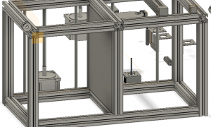
I first created a virtual model with fusion 360. Doing it directly via fusion 360 helps me with creating immediate 3D objects that will attach to the SLS printer. The SLS printer is going to be build out of aluminium and 3D printed parts (PLA and Nylon). It is also possible to test the actual mechanics of the SLS printer via fusion 360.
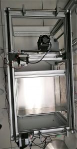
The frame
My frame is made from 30×30 aluminium profiles and everything is hand cut. It took longer than expected to saw the profiles because I cannot saw straight lines. The profiles are then mounted together with metal corner connection and 3D printed connections.
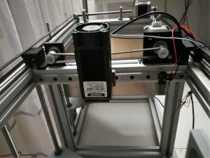
The laser component
Commercial SLS printers usually use a galvanometer to steer the laser beam. But good quality galvanometers are expensive and is one of the reasons why these printers are so expensive also, I am unexperienced with galvanometers, so I want to try a more economical and simpler mechanism. For my first version I want to use the basic cartesian mechanism. The laser component moves like a FDM extruder in the x and y direction. The disadvantages of adopting the cartesian mechanism is speed and precision.
My strategy of combatting these problems is by using high resolution stepper motors and drivers and a two in one moving bar. To explain the moving bar, I first must discuss the z-axis.
The z-axis
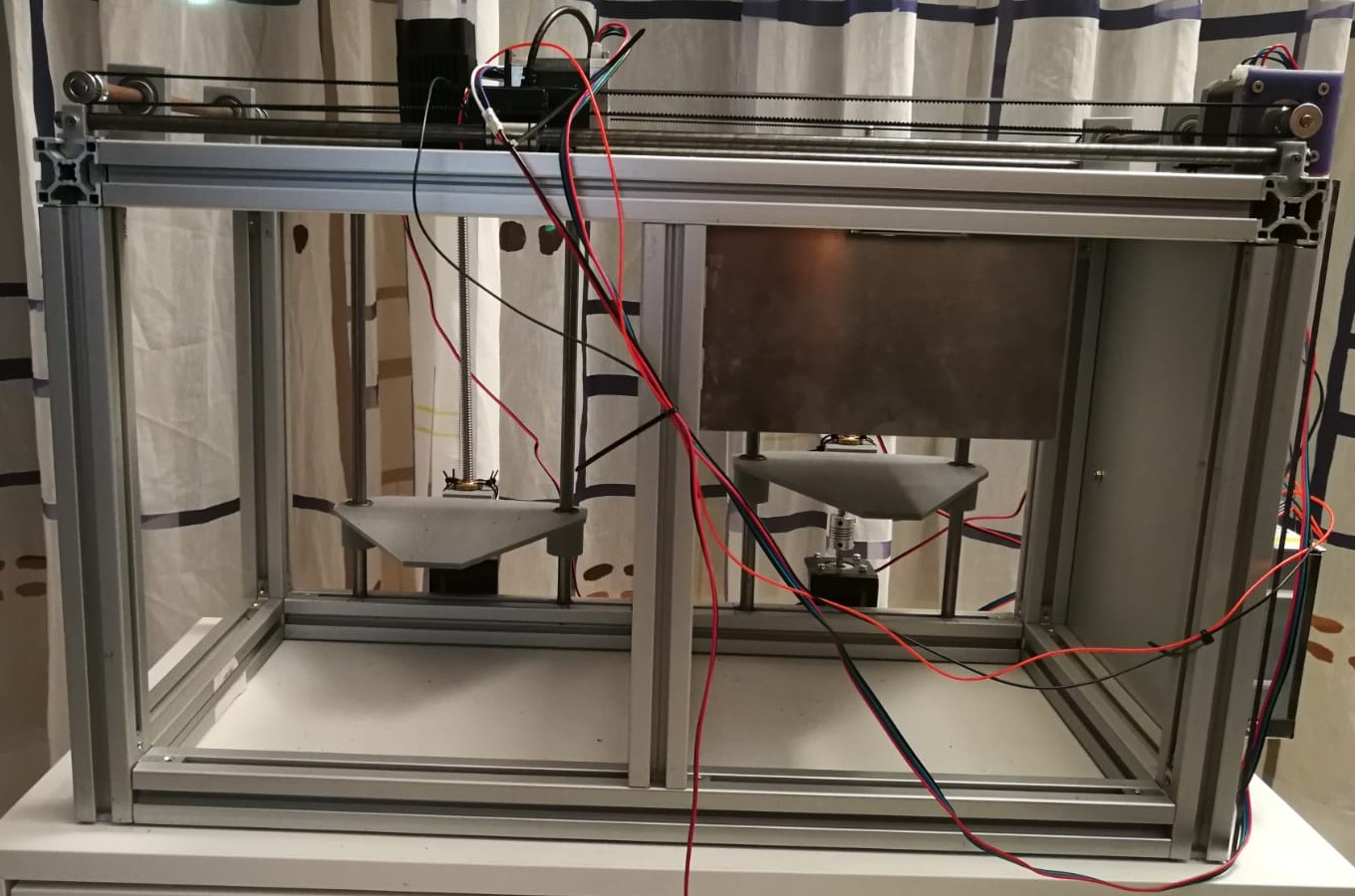
The only axis I have not talked about is the z-axis. That is because the z-axis is the biggest design challenge for the SLS printer. The first problem is that the z-axis exists out of two compartments. The first compartment is a powder feeder and the second one will contain the 3D printed model. This brings challenges to programming the software and calibration between the two chambers. The second problem has to do with heat. A SLS printer usually prints with Nylon which warps quickly if the chambers are not heated. As a result, the chambers should be made from conductive material with a high melting point like aluminium. This adds more costs to the printer. The last problem is the powder. Powder likes to end up everywhere, so the chambers should be tightly sealed. My solution for these problems is a laser cut aluminium base with a moving base that has a silicon seal around it. Think of it like a syringe. I designed the chamber via fusion 360 and sent it to a local laser cutter company.
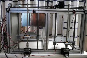
The moving bar
The moving bar moves the powder from the feeder compartment to the printing compartment. To speed up the printing process I placed the laser on the moving bar. As the moving bar moves back to base position (at the feeder compartment) the laser moves and prints a layer. Mechanically wise it works well but the software is a bit harder to configure.
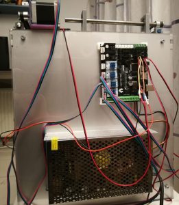
The software
The last part of the printer is the software. I am using a Megatronics V3 board with high resolution TMC2100 stepper divers and a 12 V power supply. For now, I am using mechanical end switches because the printer does not need precise bed levelling unlike FDM printers. Of course, the most important part for the SLS printer is the Laser. Surprisingly, the SLS printer does not need a high-power laser like a CO2 laser. I am using a 5 W blue laser which is already overkill. The laser is powered with TTL which can be directly hooked up to the board via an empty PWM port.
Currently I am busy configuring the universal marlin firmware to be compatible with my mechanisms. I have not yet found any opensource SLS profiles in the marlin community so when I have finished my printer I will upload my source code on this website.
Conclusion
This is currently my report on my SLS printer. Making my printer has thought me so many things about mechanics and 3D modelling. I am positive about the capabilities of my printer and the final stage the software is the next challenge I will have to solve. Now, in this website I will write updates on my printer and probably also tutorials on how to configure your own 3D printer.
The SLS printer innovated is a milestone in the 3d modeling. The mechanics and the detailed report analyzed
are remarkable.
Can i get some help with the code, i dont know how to code, thats my only drawback